
UHF RAIN RFID: Radiative Backscatter, India WPC & Global Spectrum
The dominant workhorse of global retail, logistics, and tolling: understanding the mathematical physics of electromagnetic backscatter, Friis link budgets, India WPC 865–867 MHz de-licensing rules, and high-density inventory collision protocols.
Forklift Pallet UHF Dock Portal Scan

High-throughput Gen2 RAIN portal reading 80+ tagged master cartons in under 1.2 seconds as the forklift drives through at 12 km/h.
Electromagnetic Wave Propagation
Far-Field Radiative Backscatter Physics & The 1/R⁴ Radar Profile
How passive silicon tags harvest energy from transverse electromagnetic waves and modulate reflection coefficients without a battery.
In UHF RAIN RFID (860–960 MHz), the operating wavelength λ is approximately 32.8 cm (at 915 MHz) or 34.7 cm (at 865 MHz). The Rayleigh near-field boundary is rboundary = λ / 2π ≈ 5.2 cm. Beyond 10 cm, the transponder operates exclusively in the Fraunhofer far-field radiation zone.
Forward Link: Power Harvesting by the Tag Chip
The forward electromagnetic wave propagates from the reader antenna to the tag. The power received at the tag terminals Ptag is governed by the classic Friis Free-Space Transmission Equation:
Where:
- Ptx · Gtx: Equivalent Isotropically Radiated Power (EIRP) emitted by reader.
- Gtag: Tag antenna gain (typically +1.5 to +2.1 dBi for meander dipole).
- λ: Free-space wavelength (c / f).
- R: Range distance between reader antenna and tag inlay.
- Γ: Reflection coefficient between tag antenna and chip input impedance:
Γ = (Zchip - Zant*) / (Zchip + Zant).
Reverse Link: Modulated Radar Backscatter & The 1/R4 Falloff
A passive tag possesses no onboard transmitter or local RF oscillator. Instead, the microchip communicates back by toggling an internal transistor switch across its antenna terminals, alternating between a matched absorption state (Γ ≈ 0) and an open/short reflective state (Γ ≈ 1).
This modulates the tag's Radar Cross Section (Δσrcs). The backscattered power reaching the reader receiver antenna Prx follows the monostatic radar range equation:
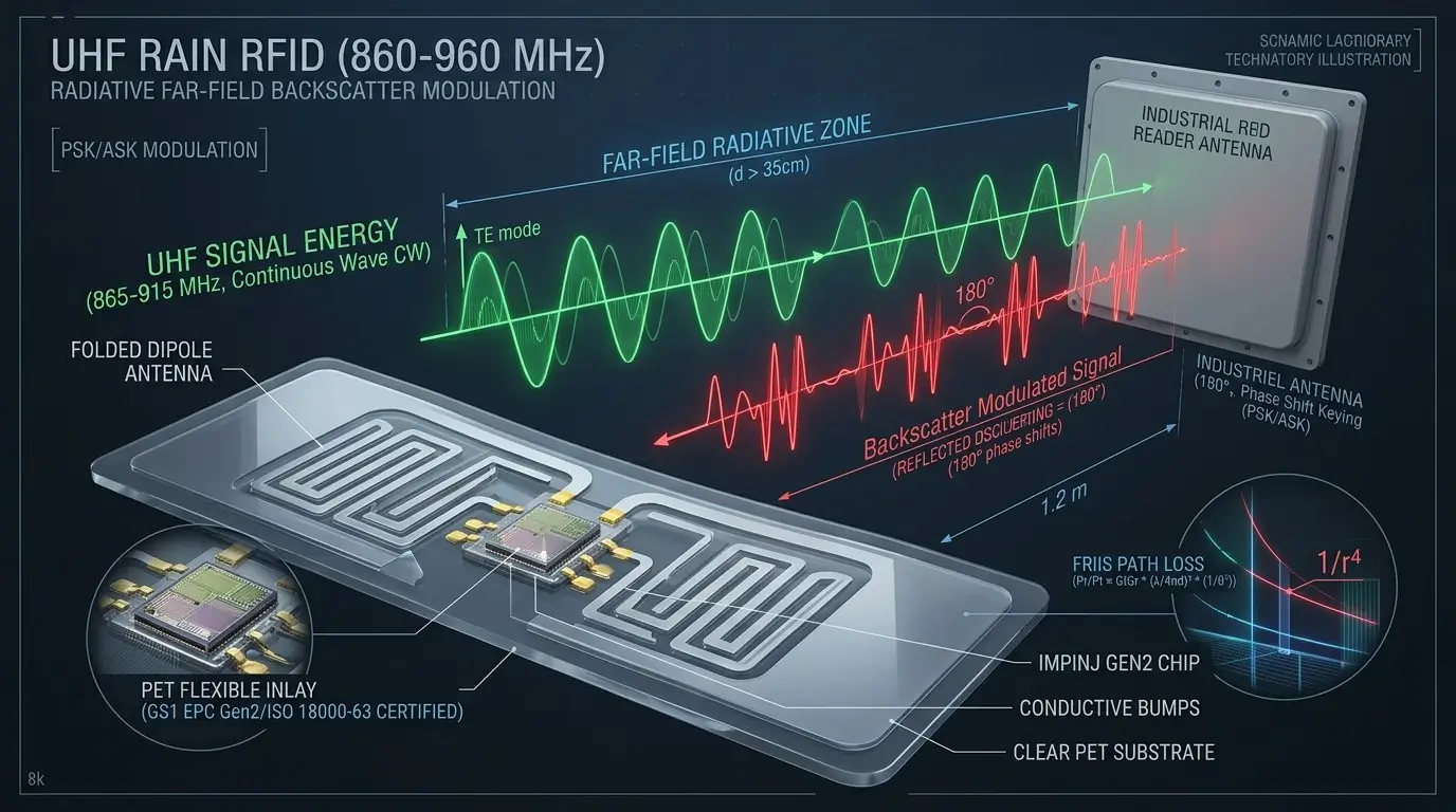
Showing T-match capacitive loop designed to conjugate-match the complex capacitive reactance of the silicon chip (Zchip ≈ 15 - j150 Ω).
Spectrum Law & Compliance
Global Regulatory Allocation: India WPC G.S.R. 564(E), US FCC Part 15 & ETSI
Legal frequency bands, maximum power thresholds, frequency hopping rules, and import Equipment Type Approval (ETA) standards.
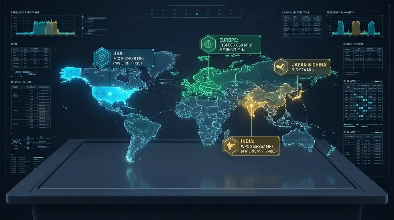
🇮🇳 India: WPC Gazette Notification G.S.R. 564(E)
In India, UHF RFID is governed by the Wireless Planning and Coordination (WPC) Wing of the Ministry of Communications. Under Gazette Notification G.S.R. 564(E):
Note: Operating foreign RFID equipment configured for the US FCC band (902–928 MHz) inside India is a violation of the Indian Telegraph Act, as 902–928 MHz overlaps with critical cellular GSM/CDMA bands!
| Jurisdiction | Frequency Band | Bandwidth | Max Transmit Power | Spread Spectrum / Hopping | Governing Standard |
|---|---|---|---|---|---|
| 🇮🇳 India | 865.0 – 867.0 MHz | 2.0 MHz | 4.0 W ERP (~6.56 W EIRP) | FHSS or Single Channel | WPC G.S.R. 564(E) |
| 🇺🇸 United States | 902.0 – 928.0 MHz | 26.0 MHz | 4.0 W EIRP (1 W Conducted) | Mandatory FHSS (50 channels, max 400ms dwell) | FCC Part 15.247 |
| 🇪🇺 Europe (ETSI Lower) | 865.6 – 867.6 MHz | 2.0 MHz | 2.0 W ERP (3.28 W EIRP) | Listen Before Talk (LBT) | ETSI EN 302 208 |
| 🇪🇺 Europe (ETSI Upper) | 915.0 – 921.0 MHz | 6.0 MHz | 4.0 W ERP | 4 Interleaved High-Power Channels | ETSI EN 302 208 (2018+) |
| 🇨🇳 China | 920.5 – 924.5 MHz | 4.0 MHz | 2.0 W ERP | Mandatory FHSS (16 channels) | SRRC Standards |
Hardware Portal Engineering
Warehouse Portals & Antenna Polarization Matching
Linear vs Circular polarization tradeoffs, 3 dB axial ratio penalty, and portal dock gate geometry.
Circular Polarized Reader Antennas
In real-world logistics, items on pallets or conveyors pass reader antennas at random rotational angles (0° to 360°). A linear antenna aligned perpendicularly (90° cross-polarization) experiences over 20 dB signal attenuation (99% power loss), resulting in missed scans.
Circular polarized antennas (RHCP or LHCP) rotate the electric field vector constantly across 360°. This incurs an intentional 3 dB polarization mismatch loss, but guarantees reliable tag powering regardless of how the carton tag is oriented!
On-Metal Standoff Engineering
Conductive metals act as electromagnetic reflectors. The tangential component of the electric field at a perfect conductor boundary must be zero (Etangential = 0). When a standard paper tag is stuck flush to a metal drum, the tag's antenna is shorted out.
Industrial On-Metal Tags incorporate a high-dielectric ceramic substrate (FR4 or ceramic, εr ≈ 9.8) with 3 mm to 5 mm thickness. The tag creates a microstrip patch or inverted-F antenna (PIFA), utilizing the metal asset underneath as an extended ground plane to actually boost antenna gain up to +3 dBi!
Storefront Hardware Catalog
Certified UHF Hardware & Middleware Integrations
Explore high-power fixed 4-port readers, enterprise handheld scanners, and industrial RAIN inlays.
4-Port / 8-Port Enterprise Fixed Gateways
Impinj R2000/E710 powered fixed readers capable of +33 dBm transmit power, LLRP protocol, and direct GPIO photocell trigger sync.
Chainway C72 & Zebra RFD40 Handhelds
Android enterprise handheld sleds with circular polarized antenna, 15-meter read reach, and pre-integrated OpenRFID middleware SDK.
Virtual RFID Link Budget Calculator
Compute EIRP, cable dB loss, path loss, and predicted read range across different antenna gains and reader sensitivity thresholds.
Frequently Asked Questions
UHF RAIN RFID Engineering FAQ
Technical answers regarding WPC compliance, backscatter link budgets, and anti-collision algorithms.
What is the official legal UHF RFID frequency band in India? ↓
How does UHF far-field radiative backscatter differ from inductive coupling? ↓
What is the Friis transmission equation for UHF radar backscatter? ↓
Why do standard UHF tags fail on metal and liquid? ↓
What are the latest silicon IC advancements in RAIN RFID? ↓
ISO 14443 vs ISO 15693, smart cards, and anti-metal ferrite shielding.
Electronic toll collection (ETC), DSRC protocols, and narrow beamforming gantries.