
Microwave RFID: High-Speed Tolling, DSRC & Microstrip Beamforming
Why high-speed expressways, electronic road pricing (ERP), and multi-lane free-flow (MLFF) gantries depend on 5.8 GHz Dedicated Short-Range Communications: microstrip patch beam containment, Doppler frequency tracking at 160+ km/h, and high-throughput data rates.
Automated Highway Gantry Tolling

High-speed electronic tolling gantry capturing encrypted transponder ID within a 15-millisecond interrogation window without vehicle deceleration.
Antenna Array Architecture
Microstrip Patch Beamforming & The Prevention of Cross-Lane Ghost Reads
How the ultra-short 5.17 cm wavelength enables narrow beamforming cones that isolate individual highway lanes.
In open multi-lane highway tolling (such as Singapore's ERP, Japan's ETC 2.0, and European CEN DSRC corridors), cars and commercial trucks travel across adjacent 3.5-meter highway lanes at speeds exceeding 120 km/h with zero physical barriers or toll booths.
The Problem with UHF Broad-Beam Antennas
Standard UHF antennas operating at 865–915 MHz possess wavelengths of ≈ 33 cm. Achieving a narrow 15° beam at UHF requires an antenna array over 1.5 meters wide, which is mechanically cumbersome and prone to wind-load deflection. Standard commercial 9 dBi UHF antennas exhibit broad 65° to 70° 3 dB beamwidths.
In an open 4-lane gantry, a 70° UHF beam illuminates multiple adjacent lanes simultaneously. A reader overhead Lane 1 risks triggering a payment debit on a transponder in Lane 2—a catastrophic failure known as a Cross-Lane False Read.
The 5.8 GHz Microstrip Solution
At f = 5.8 GHz, the wavelength shrinks to just λ = 5.17 cm. A compact planar array of microstrip patch antennas measuring just 25 × 25 cm easily achieves:
- Extremely Narrow Half-Power Beamwidth (HPBW): Down to 10° – 15° in both azimuth and elevation.
- Strict Spatial Footprint: At a standard gantry mounting height of 5.5 meters, a 14° beam illuminates an elliptical ground footprint measuring strictly 2.8 × 3.2 meters—perfectly bounded inside a single lane!
- High Antenna Gain: Directional gains reaching +15 dBi to +18 dBi, compensating for higher free-space path loss.
d = 2 · h · tan(θ / 2). For h = 5.5 m and θ = 14°, d = 2 × 5.5 × tan(7°) ≈ 1.35 meters. Vehicles in neighboring lanes remain completely invisible outside the antenna main lobe.
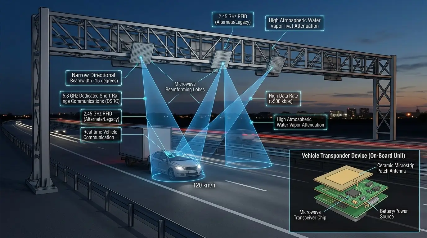
Overhead gantries house dedicated 5.8 GHz DSRC transceivers calibrated per lane, synchronized with high-resolution ALPR license plate enforcement cameras.
- • ISO 14906: Electronic Fee Collection (EFC) Application Interface
- • EN 12253 / 12795 / 12834: 5.8 GHz DSRC Physical & Data Link Layer
- • IEEE 802.11p: Wireless Access in Vehicular Environments (WAVE)
High-Velocity RF Dynamics
The Doppler Effect: Frequency Shift & Phase Tracking at Expressway Speeds
Mathematical modeling of carrier frequency compression and receiver AFC tracking loops for moving vehicles.
When a vehicle moves past a fixed overhead tolling gantry at velocity v, the relative velocity alters the observed frequency of the electromagnetic carrier wave. Because the radar wave travels from the gantry to the vehicle and scatters back, the total two-way Doppler shift Δf is given by:
Where:
- v: Vehicle forward velocity in meters per second (e.g., 160 km/h = 44.44 m/s).
- f0: Microwave carrier frequency (5.8 × 10⁹ Hz).
- c: Speed of light in vacuum (3.0 × 10⁸ m/s).
- θ: Angle between the vehicle trajectory vector and the gantry radar beam line-of-sight (typically 45° as the car enters the beam).
Calculation for a 160 km/h Expressway Vehicle:
As the vehicle passes directly beneath the gantry, θ shifts from 45° approaching (+1,215 Hz) to 90° overhead (0 Hz) to 135° departing (-1,215 Hz). This creates a dynamic Doppler frequency inflection curve (Δfspan ≈ 2.43 kHz) over an interval of mere hundreds of milliseconds.
Without dynamic Automatic Frequency Control (AFC) tracking and Costas loop carrier recovery, this phase rotation would rotate constellation points in PSK/QAM modulations, causing burst bit errors and transaction timeouts.
Atmospheric & Rain Attenuation
At 5.8 GHz, atmospheric water droplets cause Rayleigh scattering. During torrential tropical monsoons (rainfall rates > 50 mm/hr), specific attenuation reaches:
While negligible over short 6-meter gantry links, surface water sheeting across a dirty car windshield adds up to 2.5 dB of insertion loss. Tolling systems engineer a minimum 12 dB link margin to guarantee 99.999% transaction reliability in monsoons.
Comparative Spectrum Analysis
Parametric Engineering Comparison: UHF 865 MHz vs 2.45 GHz vs 5.8 GHz
Analyzing tradeoffs in tag cost, beamwidth control, data rate, and tolerance to environmental moisture.
| Specification | UHF RAIN (865–915 MHz) | Microwave (2.45 GHz ISM) | Microwave DSRC (5.8 GHz) |
|---|---|---|---|
| Wavelength (λ) | 32.8 – 34.7 cm | 12.24 cm | 5.17 cm |
| Lane Confinement Ability | Poor (Broad 65° beam) | Moderate (30° beam) | Superior (10°–15° beam) |
| Maximum Data Transmission Rate | 40 to 160 kbps | 250 to 500 kbps | 500 kbps to 1.0 Mbps |
| Average Tag Unit Cost | ₹5 to ₹15 ($0.08–$0.20) | ₹400 to ₹1,200 (BAP/Active) | ₹1,500 to ₹3,500 (OBU Transponder) |
| Free-Space Path Loss at 10m (FSPL) | 51.2 dB | 60.2 dB (+9 dB penalty) | 67.7 dB (+16.5 dB penalty) |
| Primary Deployment Domain | FASTag windshield stickers, supply chains, pallets | Rail car tracking, yard telemetry, baggage sortation | Multi-lane free-flow highway electronic tolling (MLFF) |
Commercial Solutions Catalog
Vehicle Tracking & Electronic Fee Collection Solutions
Explore our parking automation boom barriers, UHF windshield toll tags, and enterprise fleet management software.
RFID Vehicle Tracking & Parking Software
Automated barrier gate integration, ANPR camera fusion, FASTag scanning, and enterprise parking billing software.
Long-Range Integrated Readers
IP67 weatherized 12 dBi directional integrated readers designed for outdoor vehicle checkpoint boom gates.
Tamper-Proof Windshield Labels
Destructive break-on-removal tamper-evident inlays engineered for UV resistance and automotive laminated glass.
Frequently Asked Questions
Microwave RFID Engineering FAQ
Technical answers regarding DSRC transponders, Doppler shifts, and rain attenuation.
What are the primary frequencies and wavelengths of Microwave RFID? ↓
Why do highway toll systems use 5.8 GHz DSRC instead of passive UHF RFID? ↓
How does Doppler shift affect Microwave RFID at high vehicle velocities? ↓
What is the difference between Passive, BAP, and Active Microwave tags? ↓
What are the environmental drawbacks of 2.45 GHz and 5.8 GHz RFID? ↓
Friis backscatter equations, India WPC 865–867 MHz rules, and warehouse portals.
Industrial RTLS, ISO 18000-7 DASH7, and Li-SOCl2 battery lifespan physics.