
Resource
How to Install an RFID System
Complete engineering guide on how to install an RFID system: site survey, antenna geometry, cable loss budgets, reader tuning, GPIO wiring & commissioning.
Simulate, evaluate, or request turnkey hardware & middleware deployment
-
99.5%+
Read Accuracy Benchmark
when following calibrated antenna geometry
-
0.22 dB per meter
LMR-400 Coaxial Cable Loss
at 865–867 MHz WPC India UHF band
-
< 20 milliseconds
GPIO Trigger Latency
photoelectric beam trigger to RF active
Overview: The core phases of an industrial RFID installation
Learning how to install an RFID system properly is the decisive factor separating high-performing 99.5%+ accuracy deployments from frustrating setups plagued by dead spots and ghost reads. An industrial installation—whether at warehouse dock doors in Bhiwandi, factory conveyor belts in Manesar, or retail entrance gates in Mumbai—demands a disciplined 8-phase engineering sequence: pre-installation RF spectrum scans, antenna geometry design, coaxial loss budgeting, reader power floor tuning, GPIO trigger wiring, edge middleware configuration, and dynamic tag validation.
Phase 1: Conducting the pre-installation RF site survey and spectrum scan
Before mounting hardware, field engineers must conduct an on-site RF spectrum analysis across the 865–867 MHz frequency band (India WPC standard). Use a handheld spectrum analyzer to detect ambient electromagnetic interference from neighboring cellular towers, unshielded variable frequency drives (VFDs), welding equipment, and high-voltage power lines. Identify metallic support beams, metal mesh fences, and liquid storage containers that could cause signal attenuation or unwanted RF reflections.
Phase 2: Antenna mounting geometry, height, and polarization alignment
Antenna positioning dictates the shape and intensity of the interrogation zone:
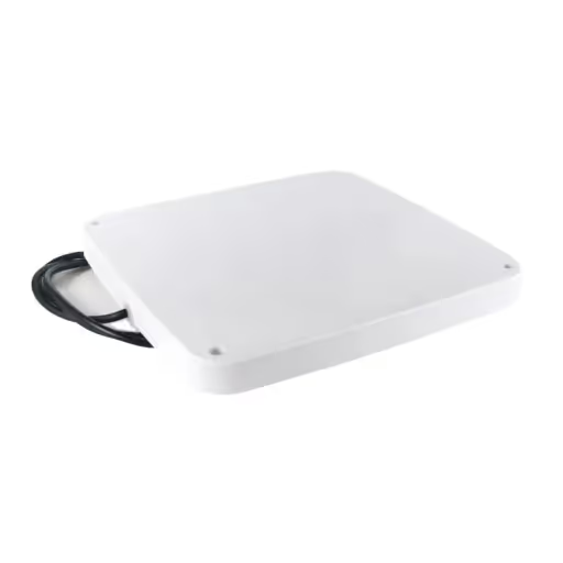
- Dock Door Portals: Install a 4-antenna cross-polarized circular array (9 dBi gain) on vertical aluminum bollards flanking the dock door. Position lower antennas at 1.0m to 1.2m height and upper antennas at 1.8m to 2.2m height, tilted 15 to 30 degrees inward toward passing pallets.
- Conveyor Lines: Mount downward-facing narrow-beam antennas 30cm to 50cm above the belt line, shielded with ferrite backing panels to isolate the reading zone to a single carton at a time.
- Circular vs. Linear Polarization: Always use circular polarized antennas for portal and warehouse setups to read tags regardless of whether they are oriented vertically or horizontally.
Phase 3: Coaxial cable loss calculations (LMR-240 vs. LMR-400)
Coaxial cable quality directly impacts radiated RF power. At 865 MHz, low-grade RG-58 cable loses 0.55 dB per meter (a 10m run loses over 70% of RF power!). For professional installations, always specify double-shielded LMR-400 low-loss coaxial cable (attenuation: 0.22 dB/meter) with gold-plated RP-TNC to N-Type connectors. Keep cable runs under 8 meters per antenna whenever possible to maintain maximum reader sensitivity.
Phase 4: Fixed reader power floor calibration and LLRP protocol configuration
A common mistake in RFID installation is setting fixed readers to maximum power (30 dBm / 1 Watt) by default. Overpowering causes RF bleed-through, reading tags on adjacent storage racks 15 meters away (ghost reads). Calibrate the reader transmit power (typically 21 dBm to 26 dBm) to contain the read zone strictly within the door frame. Configure the Low Level Reader Protocol (LLRP) session flags (Session 1 or Session 2) to prevent repetitive tag reports from stationary pallets.
Phase 5: Wiring GPIO light stacks, photocell sensors, and audible buzzers
To prevent readers from radiating RF power continuously (which creates ghost reads and RF heating), connect optical break-beam sensors (such as Omron E3Z series) to the reader's General Purpose Input (GPI 1). The reader transmits RF only when a forklift or pallet breaks the light beam. Wire the reader's General Purpose Output (GPO 1 & 2) to a multi-color industrial LED light stack: Green = Successful Scan & ASN Match; Red/Buzzer = Discrepancy or Unrecognized Tag.
Phase 6: Network infrastructure, PoE+ switches, and industrial power grounding
Connect fixed readers via shielded Cat6 Ethernet cabling to an industrial PoE+ (802.3at) network switch capable of supplying 30W per port. Ensure that all reader chassis, antenna brackets, and mounting bollards are bonded to clean building electrical earth ground (resistance < 2 Ohms) with copper grounding braid to protect sensitive RF amplifiers against lightning and static surges.
Phase 7: Edge middleware deployment, deduplication, and ERP sync
Deploy our OpenRFID Edge Middleware on an on-premise industrial IPC or edge gateway. Configure dynamic tag deduplication windows (e.g., 3-second debounce timers) and RSSI signal strength filters. The middleware aggregates hundreds of raw tag observations into a single clean JSON transaction and posts it directly to your ERP database (SAP, Tally, Zoho) via REST API or TCP sockets.
Phase 8: Static and dynamic tag reading validation tests
Commissioning requires rigorous validation: 1) Static Tag Grid Test: Place tagged cartons at 9 grid positions across a pallet to confirm zero blind spots; 2) Dynamic Speed Test: Drive a loaded forklift through the dock portal at 10 km/h to confirm 100% read capture; 3) Adjacent Lane Test: Move tagged items through the neighboring dock door to verify zero ghost-read cross-talk.
Troubleshooting common installation mistakes: Ghost reads and RF multipath
If ghost reads occur: lower reader transmit power by 2 dBm increments, re-angle antennas away from reflective metal surfaces, and add physical ferrite-backed RF absorbing curtains. If missed reads occur: check coaxial connector tightness, verify antenna cable impedance (50 Ohms), and test tag silicon sensitivity on the specific product packaging.
Hardware installation labor and site survey costs in India
A standard 2-portal warehouse installation in India—including 2 fixed 4-port readers, 8 panel antennas, LMR-400 cabling, optical sensors, light stacks, and engineering commissioning—typically costs between ₹2,20,000 and ₹3,80,000 for hardware and ₹35,000 to ₹60,000 for turnkey installation labor. Explore our complete RFID Turnkey Hardware Installation Services.
Frequently asked questions about industrial RFID system installation
Answers to key engineering questions regarding cable lengths, lightning surge suppression, antenna polarization, and portal spacing in Indian industrial facilities.
Interactive RFID Engineering Tools & Calculators
Use our free interactive calculators and simulators to model RF physics, calculate link budgets, estimate ROI, and configure EPC tags.
RFID ROI & Payback Calculator
Calculate 12-month return on investment, shrinkage reduction, and labor hours saved for your facility.
RFID Project Cost Estimator
Estimate turnkey budget breakdown including readers, antennas, tags, cloud software, and on-site engineering.
Site Survey Checklist Generator
Generate a customized engineering checklist covering RF noise floors, power drops, and portal mounting requirements.
Need a custom how to install an rfid system | step-by-step setup guide deployment?
Every environment has distinct RF absorption and ERP sync constraints. Let's review your exact workflow and design an end-to-end blueprint.
Deployed hardware & software
Products & Hardware Deployed in This Solution
Discover the professional-grade RFID readers, tags, and custom integration software systems implemented in this deployment.

Fixed RFID Reader India and UHF 4-Port Reader Portals
Four-port readers for portals and lines

RFID Handheld Reader Software for AUTOID Mobile Terminals
Android app for seamless RFID data capture

NXP U9 Flexible Printable On-Metal RFID Label 80x40mm
1.0mm Flexible Foam On-Metal Smart Label with 6.5m Read Range for IT Assets & Metallic Surfaces
Frequently asked questions
How far can an RFID antenna be placed from the fixed reader?
How do you prevent dock portals from reading tags in adjacent dock doors?
What is the required electrical power and networking for a fixed RFID portal?
Do RFID installations require government wireless licenses in India?
How long does a standard warehouse RFID portal installation take?
What happens during a network outage? Will the portal stop reading?
Discover more
You may also like
Hand-picked articles and pages worth your time next.
Fixed RFID Reader India and UHF 4-Port Reader Portals
Buy fixed RFID reader India models (865-867 MHz). High-performance 4 port UHF reader for dock doors and conveyor systems. Inquire online now.
UHF Fixed Reader Antenna and Circular Polarized Panel
Optimize signal range with UHF fixed reader antenna. High-gain panel RFID antenna with circular polarization for warehouse portals. Shop now.

RFID Site Survey & Feasibility Services
Professional on-site RF spectrum analysis, metal/liquid interference testing, antenna geometry planning, and tag read rate benchmarking across Indian warehouses and factories.

Turnkey RFID Installation Services in India | Portals & Hardware Setup
Professional on-site RFID installation services across India. Certified RF field engineers for dock doors, conveyor tunnels, antenna mounting, spectrum analysis, commissioning, and AMC in Noida, Mumbai, Bengaluru, Pune, and Chennai.